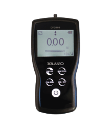
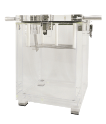
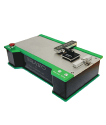
Fire Resisting Characteristics of Electrical Cables Apparatus
What It's For
What It's For
Circuit Integrity Under Fire Conditions Apparatus
What It's For
FTT produce the BS 6387 test apparatus required for testing cable circuit integrity under fire conditions.
The apparatus is supplied with ability to assess:
- Resistance to Fire Alone (IEC 60331-11 / BS 6387 Protocol C)
- Resistance to Fire with Water (BS 6387 Protocol W)
- Resistance to Fire with Mechanical Shock (BS 6387 Protocol Z)
Resistance to Fire Alone Testing (as prescribed in BS 6387 Protocol C; IEC60331-11)
Resistance to Fire with Water (BS 6387 Protocol W)
Resistance to Fire with Mechanical Shock (BS 6387 Protocol Z; IEC60331-11; BS EN 50200)
Indicative Fire Resistance Test Furnace
What's for
The fire resistance properties of a material can be used to consider its behaviour when subjected to specific heating conditions. The FTT Indicative Test Furnaces use only a fraction of the material required with the large full scale furnaces and provide a method of quantifying the ability of a material or assembly to withstand exposure to high temperatures. This furnace is also ideal for evaluating the fire performance of dampers and penetration seals for building services. FTT supply two Indicative Fire Resistance Test Furnaces with internal chambers of 1000 mm (W) × 1000 mm (H) × 1000 mm (D) or 1500 mm (W) × 1500 mm (H) × 1500 mm (D).
Four sides of the walls are lined with special high temperature insulating fire bricks on the hot face and pre-cast refractory castables at the edges exposed to the specimen restraint frame as well as mineral boards on the cold face.
Horizontal Fire Resistance Test Furnace
What's for
Hydraulic Tilting Fire Resistance Test Furnace
What's for
The FTT Fire Resistance Test Furnace for Vertical and Horizontal Test Specimens is the apparatus needed to evaluate the fire resistance of a horizontal or vertical construction assembly, column, or support, and provides a method of quantifying the ability of products such as doors and dampers, and building materials to withstand exposure to high temperatures. This is done by evaluating a number of performance elements such as; the load-bearing capacity, the ability to provide fire containment and the thermal transmittance of the materials and systems.
- Fire Resistance Test Furnace with an internal chamber measuring 3000mm (W) × 4000mm (H) × 1000mm (D)
- The capability of carrying out test on vertical and horizontal test specimens that are mounted on custom made restraint frames.
- A Hydraulic Tilting System is provided to enable the Furnace to be positioned either upright for testing items such as walls and doors, or on a horizontal plane for testing floors and ceilings.
- A furnace refractory lining comprised of insulating fire bricks, refractory castables and mineral boards. The roof is lined with profiled bricks and anchored with cast refractories in situ.
- A furnace casing made of mild steel plates reinforced with steel C-Channels, I-Beams and steel sections to counter structural distortion due to heat-steel casing lined with mineral fibreboard on the cold face and refractory insulating bricks anchored back to the wall with high temperature cast in-situ blocks, on the hot face.
- 4 sets of viewing ports made of heat resistant quartz glass are placed at strategic locations on the long side wall. This will enable the operator to view the complete test specimen during a fire test.
- A lightweight alumina fibreboard sliding door enclosed within the insulated, air-cooled frame. This will shield off the furnace heat when the viewing ports are not in use.
- 20 sets of Refractory Nozzle Mix Burners. Each burner will have a flame supervision unit to ensure that all combustion units operate on a fail safe mode at all times. 10 burners are installed on each of the left side and right side of the furnace wall. Each burner is designed to use liquefied petroleum gas.
- A Furnace Combustion Control Panel designed to operate on both fully automatic and manual control modes.
- Automatic ignition of the burners is through the use of one push button switch. This fires up the burners based on a preset heating curve, such as that described in BS 476 Parts 20-24, EN 1363 and the IMO Hydrocarbon Curve. Manual burner control enables individual burners to be ignited at will.
- BS 476 (20-24)
- BS EN 1363 (1-2)
- BS EN 1364 (1-2)
- BS EN 1365 (1-4)
- BS EN 1366 (1-3)
- BS EN 1634-1
- ASTM E119
- ASTM E814
- ASTM E1966
- UL 263
- UL 1709
- UL10 (B-C)
- UL 1479
- UL 2079
- ISO 834 (1, 4-9)
- ISO 6944 (1-2)
- ISO 3008
- ISO 3009
Large Scale Vertical Fire Resistance Test Furnace
What's For
- A Fire Resistance Test Furnace with an internal chamber measuring: 3000mm (W) × 3000mm (H × 1300mm (D)
- The capability to carry out test on Vertical Test Specimens that are mounted on custom made restraint frames.
- Refractory lining is comprised of insulating fire bricks, refractory castables and mineral boards.
- A roof lined with profiled bricks and anchored with refractories cast in situ.
- A casing made of mild steel plates reinforced with steel C-Channels, I-beams and steel sections to counter structural distortion due to heat.
- A specimen restraint frame mounted on the front end of the furnace and secured by a minimum of 4 sets of door clamps.
- A steel casing lined with mineral fibreboard on the cold face and refractory insulating bricks anchored back to the wall with high temperature cast in-situ blocks, on the hot face.
- 4 sets of viewing ports made of heat resistant quartz glass are provided at strategic locations on the long side wall. This will enable the operator to view the complete test specimen during a fire test.
- A sliding door made of light weight alumina is enclosed within an insulated, air-cooled frame. This will shield off the furnace heat when the viewing ports are not in use.
- 12 sets of Special Luminous Flame Burners. Every burner has a flame supervision unit to ensure that all combustion units operate on a fail safe mode at all times.
- Furnace Combustion Control Panel is designed to operate on both fully automatic and manual control modes. Automatic ignition of the burners is through the use of one push button switch, this, fires up the burners based on a preset heating curve, as described in BS 476 Parts 20-24, EN 1363 and the IMO Hydrocarbon Curve. Manual burner control enables individual burners to be ignited at will.
- BS 476 (20-23)
- BS EN 1363 (1-2)
- BS EN 1364 (1)
- BS EN 1365 (1)
- BS EN 1366 (1-3)
- BS EN 1634-1
- ASTM E119
- ASTM E814
- UL10 (B-C)
- UL 263
- UL 1709
- UL 1479
- UL 2079
- ISO 834 (1, 4, 8)
- ISO 3008
- ISO 3009


